Overview
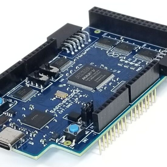
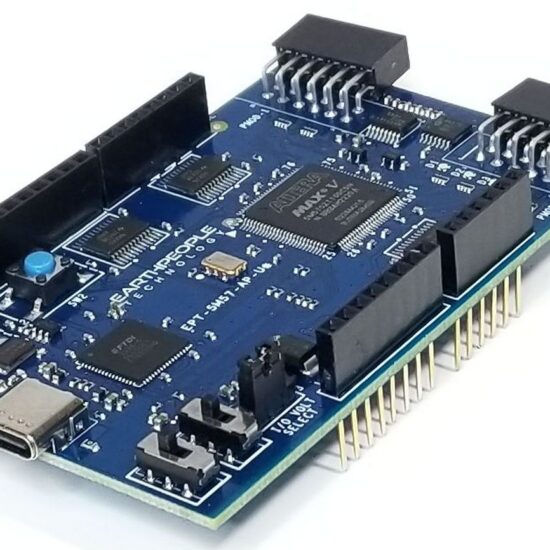
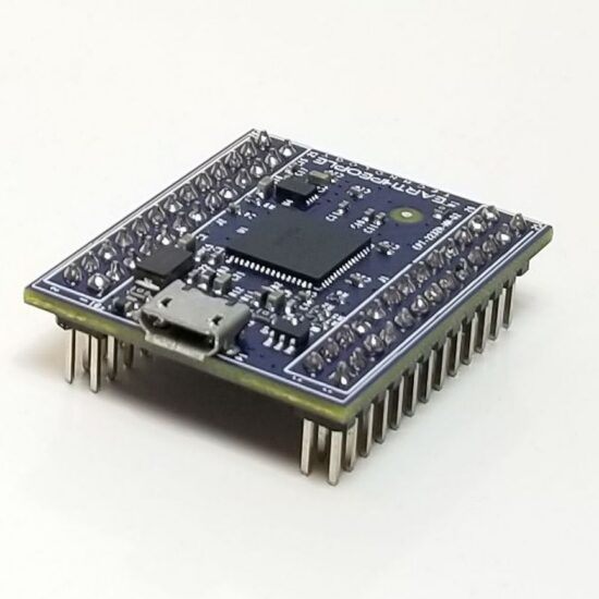
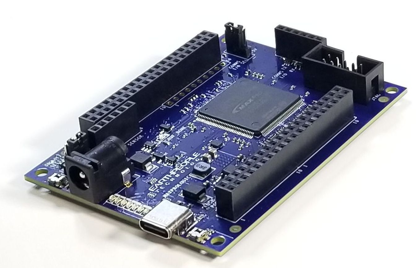
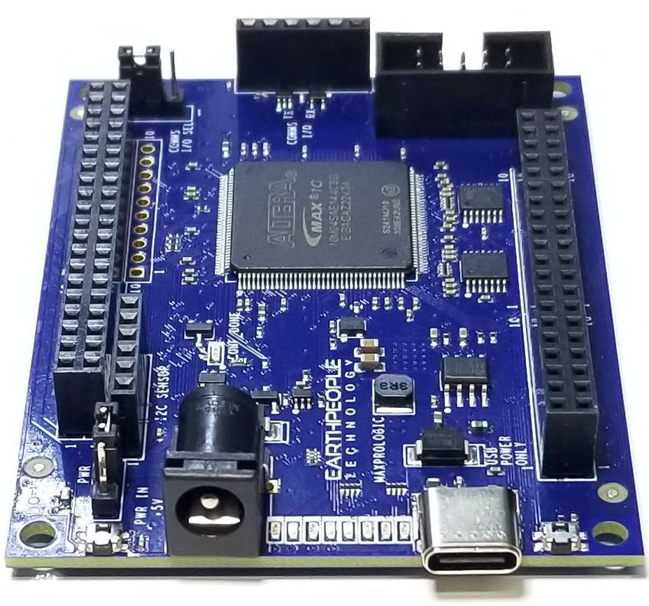
The MaxProLogic is designed to make digital design easy and cost effective. At Terranologic we have years of experience helping students and hobbyists get started with FPGA design. We know that the learning curve in getting started can be a time consuming and frustrating event. So, we created a User Manual that walks the user from unpacking to creating the first project to creating an epic project that will get attention.

The core of the MaxProLogic is the Altera MAX10 FPGA. This powerful chip has 4,000 Logic Elements and 200Kbits of Memory. The MAX10 is easily scalable from the entry level college student to the most advanced projects like an audio sound meter with FFT.
Upon the many great features of the MaxProLogic is the MAX10 chip has a built in Flash for configuration and incorporates 8 channels of Analog to Digital Conversion. These two features alone create a far superior FPGA chip than any competitor on the market. It allows the user to create more diverse projects.
MaxProLogic FPGA Development System
- MAX 10 10M04SA FPGA From ALTERA
- 4,000 Logic Elements; 2.2 Mbit On chip Flash; 189 Kbit On Chip SRAM
- 8 Analog Input Channels; 12 bit; 1MSamples/Second
- 65 Available I/O’s at connectors
- 8 Green User configurable LEDs
- 1 Power Pushbutton Switch; 1 User Configurable Pushbutton Switch
- On Board SD Card Slot
- Two Power options: Standard USB (+5V @ 2Amp) Using USB-C connector
- 5mm Barrel Connector Accepts +12V @ 3Amp
- Switching Power Supply, Provides stable output under high load stress
- On Board 50MHz Oscillator
- On board interface to Standard USB to Serial Adapters

Why the MaxProLogic?
The MaxProLogic is designed to make digital design easy and cost effective. At Terranologic we have years of experience helping students and hobbyists get started with FPGA design. We know that the learning curve in getting started can be a time consuming and frustrating event. So, we created a User Manual that walks the user from unpacking to creating the first project to creating an epic project that will get attention.
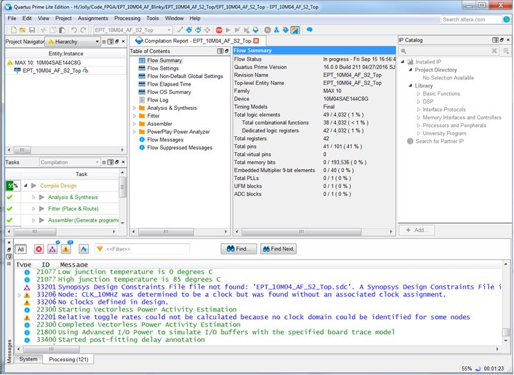
The Learning Curve with any new piece of hardware is always time consuming. We painstakingly crafted a guide that leaves out no details in creating a project under the Quartus Software Tool. We will explain how to organize project user files into a folder system for easy navigation. We will explain how to:
- Create a Project
- Add User Files
- Add MegaFunction IP Files
- Add Synopsys Design Constraints,
- Assign Inputs and Outputs to pins of the MAX10
- Compile the Design
- Synthesize the Project
- Program into the MAX10
In short, the MaxProLogic will cut the time to get the time to get up and running significantly. We also include several pre-made, fully compiled, fully synthesized projects for the user. You can start your project by copying one of these premade projects and adding user code.
THE MAXPROLOGIC AND SIMULATION
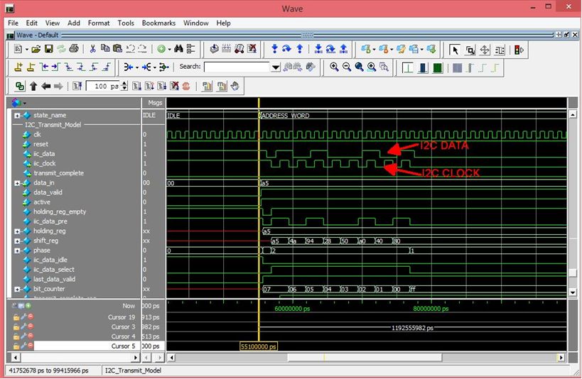
Simulation has always been a weak point for students and hobbyists. Most FPGA beginners write the user code, compile it, synthesize it, program the chip then test out the results. While this approach may work for small, simple designs, it quickly becomes a problem with larger projects. As the user code increases in complexity, better development tools are required to quickly isolate problems. The premier method for this is functional testing. ModelSim is included Free with the Quartus Prime Package. ModelSim is a powerful tool for finding errors in the user code before you go to synthesis.
Terranologic has created a guide that walks the user through creating a project and verifying functionality of user code. This guide will explain the use of the TestBench, Tasks, and Models in verification of the user code. In specifics, the guide will explain:
- Create a ModelSim Project
- Create a Makefile and Compilation of user code
- Create a TestBench and Stimulus of user code
- Add Synopsys Design Constraints
- Assign Inputs and Outputs to pins of the MAX10
- Create Models for user code to Interact With
- Add Clock Signals, Resets, and Timing Elements
- Debug the Functionality of user code
PROGRAMMING TOOLS FOR THE MAXPROLOGIC
The MaxProLogic leverages the Quartus Prime Lite Software for compilation and synethsis. This software tool is completely free and provides very powerful tools for the user. Also included free in the software tools is the simulation tool, ModelSim. A lot beginners to the FPGA world are hesitant about using simulation tools. They feel these tools are too difficult to learn and use. This is where the MaxProLogic breaks that fear. The MaxProLogic comes with a user guide that walks the user from start up to full simulation. Each step is well documented and explained.

THE MAXPROLOGIC HARDWARE
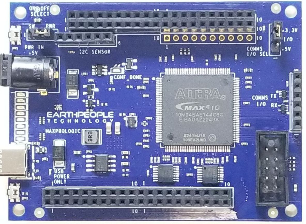
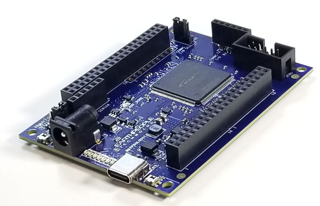
The MaxProLogic is Open Source Hardware based on the MAX10 FPGA. In addition to the on chip 8 Channel ADC and on chip Flash, the board is loaded with great tools. The board has two power options, standard USB Micro B connector and 5.5mm Barrel connector. You can run the MaxProLogic from a laptop with 2.5W of power. Or you can run it from the +5V @ 2A wall USB chargers for 10W of power. The barrel connector can handle up to +9V @ 3 A for 27W of power.
The MaxProLogic has a MicroSD connector on the bottom of the board. This allows the user to create a powerful long term Data Acquisition System. The board has an optional On/Off pushbutton switch that allows the user to turn the system on and off. There are two clocking options, 50MHz oscillator and 32.768KHz oscillator.

The block diagram shows all of the parts of the MaxProLogic. There is a main switching power supply for +3.3V. The +3.3V powers the core of the FPGA along with the Input/Outputs of the FPGA as well as provides power for user circuits.

MaxPrologic Communications
The MaxProLogic has a built in connector to allow FTDI Breakout Boards or Equivalent to connect directly to the FPGA. There are two voltage level translators that allow both +5V and +3.3V devices to communicate via UART with the FPGA.

Downloads
| 85-000012 | MaxProLogic FPGA Development System User Manual | MAX_FPGA_DEV_SYS_UM_V49.pdf |
| 95-000013 | MaxProLogic FPGA Development System Data Sheet | MAX_FPGA_DEV_SYS_DS_V44.pdf |
| 45-000013 | MaxProLogic FPGA Development System Project DVD | MAXPROLOGIC FPGA PROJECT DVD |
| 55-000013 | MaxProLogic FPGA Development System Schematics | MAXPROLOGIC_SCHEMATICS_V4.pdf |
| 35-000001 | EPT Drivers | EPT_2.08.24.ZIP |