
EARTH PEOPLE TECHNOLOGY, Inc
FAST
LED BLINKY PROJECT UnoProLogic
User Manual
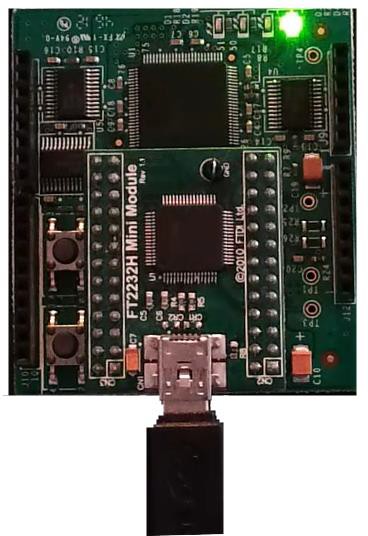
The Fast LED Blinky Project is designed for the UnoProLogic USB CPLD Development System. A controller is implemented on the Host PC. It sets one of several functions to blink the LEDs. These functions are transmitted to the UnoProLogic which along with the delay timer value blink the LED’s in one of several patterns. This user manual guides the user through the creation of the C# and Verilog code. It also walks the user through creating the project files and compiling and programming the UnoProLogic. All source files are included on the USB_CPLD_FAST_LED_BLINKY_PROJECT_CD.
Circuit designs, software and documentation are copyright © 2012-2013, Terranologic, Inc
Microsoft and Windows are both registered trademarks of Microsoft Corporation. Altera is a trademark of the Altera Corporation. All other trademarks referenced herein are the property of their respective owners and no trademark rights to the same are claimed.
Table of Contents
-
Fast LED Blinky Project Introduction
The Fast LED Blinky Project uses the Terranologic UnoProLogic USB- CPLD development system connected to a Windows PC. The project software uses the Microsoft C# Express in conjunction with the Active Host dll.
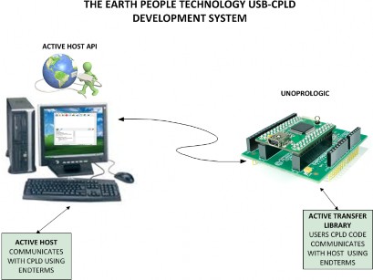
This User Manual will guide the user to create the C# application and the The Verilog code for the CPLD. There are several functions the C# application can choose from. It sends a command to the CPLD via USB. A function such as Shift Left, Count Up is selected in the CPLD code. It starts a state machine which updates the LED’s inserts a delay and starts the process over again.
This project serves as an introduction to advanced programming techniques using Verilog for programming the CPLD and C# for programming the user interface on the PC. The first two sections provide a background for the PC and CPLD libraries.
-
Driver Installation
Follow the instructions in the EPT USB CPLD Development System User Manual to install all of the software and drivers for use with the hardware.
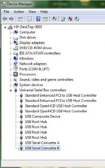
If the driver has been installed correctly, you can go to the Device Manager and click on the Universal Serial Bus controllers and see “USB Serial Converter A” and “USB Serial Converter B”.
-
Software Installation
Follow the the instructions in the EPT USB CPLD Development System User Manual to install the following software:
-
Altera Quartus II
-
Microsoft C# Express
-
-
Active Host EndTerms
The Active Host API is provided as a dll which easily interfaces to application software written in C#, C++ or C. It runs on the PC and provides transparent connection
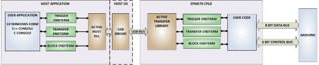
from PC application code through the USB driver to the user CPLD code. The user code connects to “Endterms” in the Active Host dll. The Host “Endterms” have
complementary HDL “Endterms” in the Active Transfer Library. Users have seamless bi-directional communications at their disposal in the form of:
-
Trigger Endterm
-
Transfer Endterm
-
Block Endterm
User code writes to the Endterms as function calls. Just include the address of the individual module (there are eight individually addressable modules of each Endterm). Immediately after writing to the selected Endterm, the value is received at the HDL Endterm in the CPLD.
Receiving data from the CPLD is made simple by Active Host. Active Host transfers data from the CPLD as soon as it is available. It stores the transferred data into circular buffer in local memory. When the transfer is complete, Active Host invokes a callback function which is registered in the user’s application. This callback function provides a mechanism to transparently receive data from the CPLD. The user application does not need to schedule a read from the USB or call any blocking threads.
-
-
Active Transfer Library EndTerms
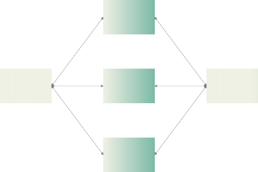
The Active Transfer Library is a portfolio of HDL modules that provides an easy to use yet powerful USB transfer mechanism. The user HDL code communicates with EndTerms in the form of modules. These EndTerm modules are commensurate with the Active Host EndTerms. There are three types of EndTerms in the Active Transfer Library:
-
Trigger Endterm
-
Transfer Endterm
-
Block Endterm
They each have a simple interface that the user HDL code can use to send or receive data across the USB. Writing to an EndTerm will cause the data to immediately arrive
ACTIVE TRANSFER LIBRARY
BLOCK ENDTERM
USER CODE
SINGLE TRANSFER ENDTERM
TRIGGER ENDTERM
at the commensurate EndTerm in the Active Host/user application. The transfer through the USB is transparent. User HDL code doesn’t need to set up Endpoints or respond to Host initiated data requests. The whole process is easy yet powerful.
-
-
-
The Development Process
The development of the Fast LED Blinky Project starts with the C# Application. The user will write the code in which to send a command and a delay time to the UnoProLogic board. The user will write the Verilog code for the CPLD which selects a function and sets the delay timer, then
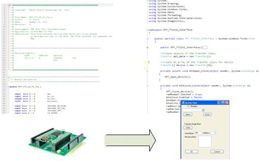
initiates and starts the state machine. The state machine will update the state of the LED’s, wait for the delay counter to reach the interval time sent by the C# application, then increment led value. The state machine repeats this process until commanded by the C# application to stop or change.
-
Designing a Simple Fast LED Blinky Project
The user should get familiarized with programming techniques using Verilog for programming the CPLD and C# for programming the user interface on the PC. For an introduction to Verilog, go to:
www.asic-world.com/verilog/intro1.html#Introduction
For an introduction to C#, go to: http://www.homeandlearn.co.uk/csharp/csharp.html
-
Fast LED Blinky Project Equipment Needed
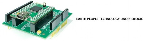
The equipment you will need for the Fast LED Blinky project is
-
Earth People Technology UnoProLogic board
-
PC running Windows 7 or equivalent, with 2 USB ports
-
USB cable Type Mini B
-
-
Fast LED Blinky Data Flow
The data flow for the Fast LED Blinky project is shown below. The C# application sits idle until the user clicks on a button. When a button is clicked, a C# event is generated. The event will select a function and send a command to the CPLD.
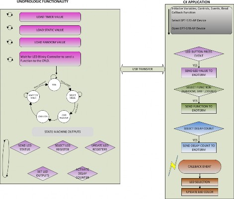
The data flow in the UnoProLogic starts with selecting a starting value by sending a four bit value to the Byte Transfer Endterm. Next, a Trigger Endterm is sent to latch this value into an internal register. The delay timer count value is sent to the CPLD in a series of two bytes on the Byte Transfer Endterm. Each byte is latched into internal registers using a Trigger Endterm. The CPLD has a state machine that stays in the idle state until one of the bits from 4 to 7 are set high in the Byte Transfer Endterm. These bits represent one of the functions of the LED Blinky. The state machine cycles through its states of updating the LED’s, waiting for delay count to finish counting, and incrementing the led state. At the completion of the cycle, the state machine repeats the process. It does this until a command is sent from the C# application to stop or change to another function.
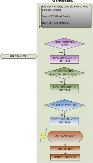
The C# data flow on the PC starts with the initialization of variables, controls, events, and read callback functions. When the application starts, the Windows Form is displayed on the PC and the system registry is scanned for any Terranologic devices. Any devices that are found are added to the drop down box. The user must then select the available EPT device and click the Open button. This will select the device and allocate all memory needed for the Active Host EndTerms. Next, the user must click on a function button. Clicking a button will initiate an event. When the user selects an LED function, a byte is sent to the CPLD which instructs the code to perform the user selected function.
Every time an LEDs in the CPLD change state, the new state is sent as a byte message from the CPLD to the Active Host EndTerm in the C# application. When the byte is received, the read callback function is called. The read callback will call the EPTParseReceive() function which calls the TransferOutReceive() function. In this function, the EndTerm is selected and the byte is decoded to set the color of the corresponding LED button on the Windows Form. If the LED is lit on the CPLD, it will be green on the Windows Form. If the LED is not lit on the CPLD, the LED button will be gray on the Windows Form.
-
-
CPLD Fast LED Blinky Coding
The UnoProLogic will accept a command from the PC and returns the current state of the LEDS to the PC. The Active Transfer Library is used to send the data to and receive from the PC. The Transfer EndTerms are used to connect the Active Transfer Library to the user code. This makes it easy to transfer data to and from the PC via the USB. The user needs to create a state machine to control the function of incrementing the LED state, updating the LED’s and waiting for a delay timer to expire.
-
Define the User Design.
In this step we will define the user’s code and include EndTerms and the EPT Active Transfer Library. The Active Transfer Library contains a set of files with a “.vqm” name extension which select particular operations to perform (e.g., byte transfer, block transfer, trigger).. The active_transfer_library.vqm file must be included in the top level file of the project. The EndTerms will connect to the active_transfer_library and provide a path to connect user code to the library. All of these files are available on the Terranologic Project CD.
ACTIVE TRANSFER LIBRARY
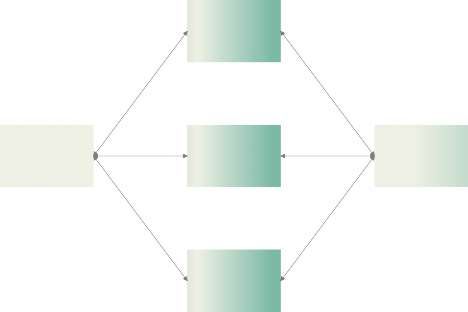
BLOCK ENDTERM
USER CODE
SINGLE TRANSFER ENDTERM
TRIGGER ENDTERM
We will build our CPLD project using Quartus II software from Altera. The primary file defining the user’s CPLD project is named “EPT_570_AP_U2_Top.v”. It defines the user code and connects the active_transfer_library, Endterms.
The Fast LED Blinky project will accept commands from the Host PC through the use of Transfer EndTerms. It will also send a response the Host PC through the Transfer EndTerms. In the user code the EndTerms look like signals in Verilog that connect the registers to leaf instantiations. Leaf instantiations are used to pass signals from one module to another, similar to functions in the “C” language. The commands are used to set up initial values and select an LED Function in the Fast LED Blinky code. The LED Functions are used to start a state machine which increments a value for the LEDS, then applies the value to the LEDs, waits in a delay loop for the delay counter to expire, then starts the process over. Each the LED’s are updated, this value is transmitted to the Host PC for display in the C# application. Because the active_transfer_library runs at 66 MHz we can run the LED’s up to a speed of 1/4 this clock speed or 16.5 MHz.
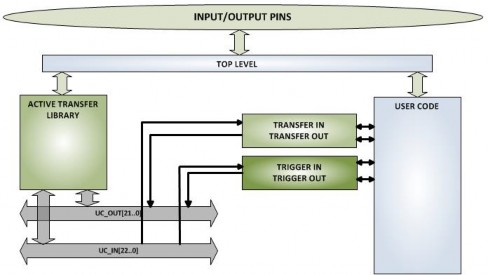
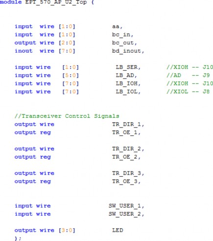
The first thing to do is to create a top level file for the project. The top level file will include the input and outputs for the CPLD. These are declared according to the Verilog syntax rules. We won’t go through all the rules of Verilog here, but feel free to explore the language more thoroughly at:
www.asic-world.com/verilog/intro1.html#Introduction
-
Select the Input/Outputs
We need to set the inputs and outputs for EPT_570_AP_U2_Top.v. The I/O nets will be used to connect the signals of the user code to the pins of the CPLD. All of the usable pins are connected to traces on the UnoProLogic board and serve specific functions.
Each net is followed by the net type wire or reg. If it is a register, the array description must be added.
-
Registers and Parameters
Next, the parameters are defined. These are used as constants in the user code.
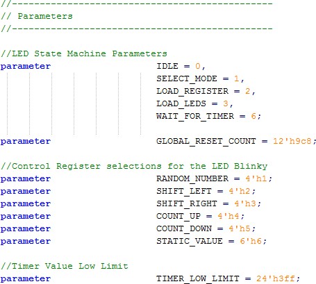
The state machine states are defined as parameters here. Also, the functions are defined. They will be used to select the appropriate function from the incoming control register.
Next is the Internal Signal and Register Declarations.
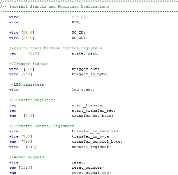
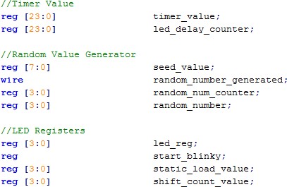
-
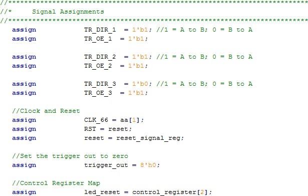
Assignments
Next, add the assignments. These assignments will set the direction of the bus transceivers. The transceivers also include an output enable bit.
-
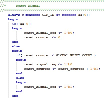
Reset Circuit
The reset signal is generated by a counter that starts counting upon power up. When the counter reaches GLOBAL_RESET_COUNT.
-
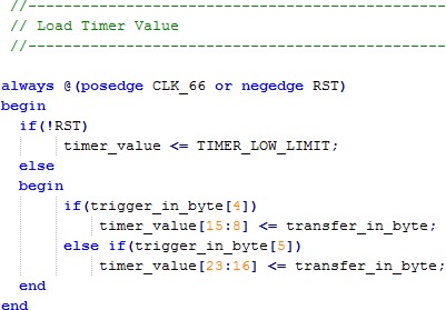
Load Timer Value
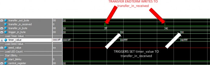
The timer_value is a 24 bit register. However, we will purposely keep the lower limit set to TIMER_LOW_LIMIT = 24'h3ff. We do this because if the state machine updates faster than this lower limit, the C# application gets overwhelmed with LED status updates and cannot process the data. So, this lower time limit keeps things from moving too fast. The update to the timer_value has to be done with two byte writes and two triggers. This first byte is transmitted from the C# application via the Active Transfer EndTerm and is received by the commensurate EndTerm in the CPLD code. The register transfer_in_byte holds the transferred byte. Next, the C# application sets the Active Trigger fifth bit. Setting this trigger bit causes the middle eight bits of timer_value to load the byte from transfer_in_byte. A second trigger bit, Active Trigger sixth bit, sets the second transfer from transfer_in_byte into the top eight bits of timer_value.
-
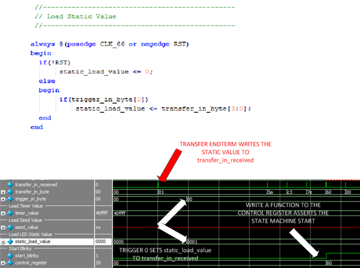
Load Static Value
The static_load_value is a 4 bit register. This value is transmitted from the C# application whenever the user presses one of the LED buttons. To latch the value into static_load_value, the C# application must set the Active Trigger bit 0. Once the static_load_value is updated, the load static value function is sent from the C# application to the CPLD. This is done by sending a command to the Control Register. Whenever a command is received through the Control Register in the CPLD code, the state machine starts and cycles through its states. As it steps into the state[SELECT_MODE] state, the led_reg is loaded with the static_load_value. The state machine will continue to the state[LOAD_LEDS] state. In this state, the LEDs are set to the value of the static_load_value. The state machine continues on to the state[WAIT_FOR_TIMER] state where it delays for the count down from the
timer_value then goes back to the state[SELECT_MODE] to branch back to state[IDLE]. In the idle state, it waits until the C# application sends another command.
-
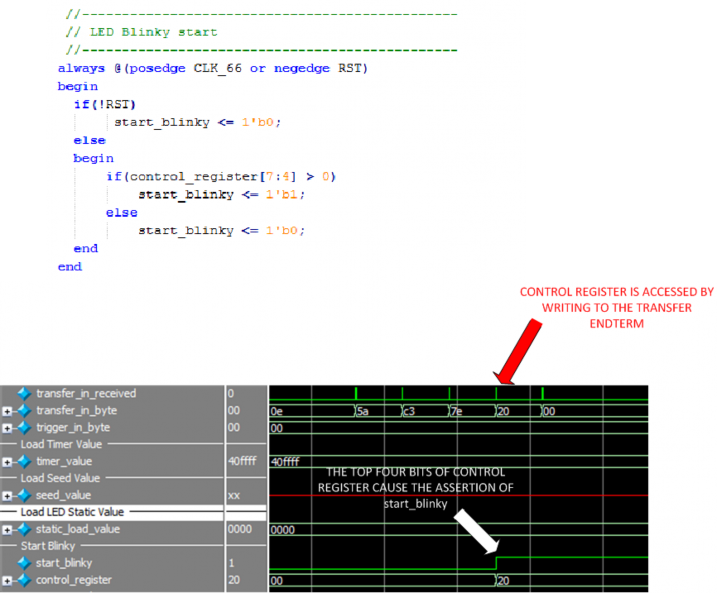
LED Blinky Start
The state machine waits in the idle state until an LED function is selected and sent from the C# application to the CPLD. This is done by sending a command to the Control Register. Whenever a command is received through the Control Register in the CPLD code, the start_blinky signal is asserted. This signal causes the state machine to start and cycles through its states. To de-assert the start_blinky signal, a 8’h00 must be sent to the Control Register.
-
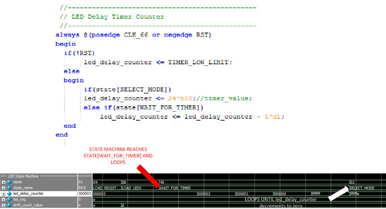
Delay Timer Count
The Delay Timer Count is used to add a delay between the changes to the LEDs. When the state machine reaches the state[WAIT_FOR_TIMER], the state machine will loop until led_delay_counter decrements to zero. The led_delay_counter is set to the timer_value when the state machine reaches the state[SELECT_MODE].
-
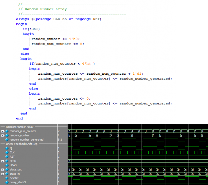
Random Number Array
The Random Number Array is a four bit register that is used to store the output of the Linear Feedback Shift Register. The Random Number Array is used to set all four LED’s to a random value. The Linear Feedback Shift Register produces a one bit random every clock cycle. The Random Number Array circuit uses a counter, random_num_counter, to capture each bit into one of the bits of the Random Number Array. The counter increments each clock cycle, When reaches 3, the random_num_counter is set to zero and the counting cycle starts over again.
-
Send Status of LEDs to Host
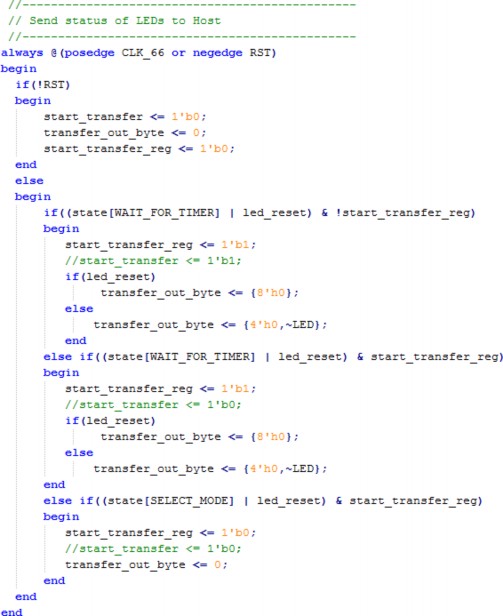
Each time the LED’s are updated, the present status of all four LED’s (on or off) is transmitted to the C# application for display on the LED buttons. This is done in the state[WAIT_FOR_TIMER] of the state machine cycle.
There are three registers used to control the Send Status of LEDs to Host.
-
start_transfer – single bit used to initiate the transfer using the Transfer Endterm
-
transfer_out_byte – eight bit byte that is transferred using the Transfer Endterm
-
start_transfer_reg – single bit used to latch the start_transfer signal.
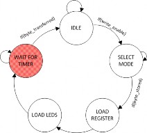
When the state machine reaches the state[WAIT_FOR_TIMER], the first if statement is entered. The start_transfer_reg and the start_transfer signals assert. The embedded if statement also executes. This if statement checks the led_reset signal. If it is high, then set the transfer_out_byte to zero, else set the bottom four bits of transfer_out_byte to the inverse of the LED’s. We set it equal to the inverse of the LEDs, because the output pins drive a zero onto the LED circuits to light them up. At the next clock cycle (CLK_66), the second if statement is entered. This if statement will de-assert the start_transfee signal. It also executes the same embedded if statement above. This is done just in case the led_reset signal was asserted after the first if statement executed.
Finally, when the state machine moves on to the state[SELECT_MODE], it causes the Send Status of LEDs to Host block to reset all registers. When the state machine moves on to the next state, the block is ready to repeat the process over again.
-
-
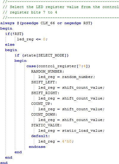
Select the LED Function From Control Register
The user will select an LED function and send it from the C# application. It sends the selected function to the CPLD via the Control Register. A state machine in the active_control_register.v file decodes this sequence and captures the fourth byte as the control register. The top four bits of the control register determine the function. There are six functions that can be selected:
-
RANDOM_NUMBER = 4'h1;
-
SHIFT_LEFT = 4'h2;
-
SHIFT_RIGHT = 4'h3;
-
COUNT_UP = 4'h4;
-
COUNT_DOWN = 4'h5;
-
STATIC_VALUE = 6'h6;
All six of the functions are updated with their incremental value during each state machine cycle. This means the random_number is updated with a new random value every fourth clock cycle, the shift_count_value is incremented by the appropriate amount per state machine cycle. Also, if an LED button was pressed in the C# application, the static_load_value will capture this new state.
When the LED state machine reaches the state[SELECT_MODE] state, a case statement is used to update the led_reg with a value that calculated based on its function. The led_reg will be used to change the LED outputs in another state.
-
-
Increment the Shift/Count Value
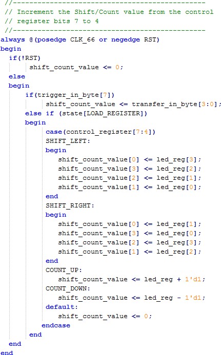
In the increment the Shift/Count Value from the Control Register block, the shift_count_value is either incremented, decremented, or shifted. The modification to the value depends on the LED function that was selected by the user. In the synchronous part of the block, the first if statement latches the value of the transfer_in_byte bottom four bits into the shift_count_value. This gives the shift_count_value an initial value to modify. This is needed because if the value is all zeros, then no shift will occur. The transfer_in_byte comes into the CPLD from the C# application through the Transfer EndTerm address 2. The value is latched by the
Trigger EndTerm bit 7. So, the C# application writes the shift_count_value to Transfer EndTerm address 2, then sets the Trigger EndTerm bit 7.
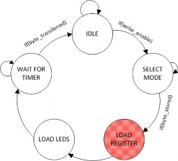
The state machine cycles to state[LOAD_REGISTER] and causes the Increment the Shift/Count value from the Control Register block to enter the second if statement. In this branch, a case statement is used to set the shift_count_value to a modified value. The case statement uses the control_register top four bits to compare to the four parameters.
-
parameter SHIFT_LEFT =4'h2;
-
parameter SHIFT_RIGHT =4'h3;
-
parameter COUNT_UP =4'h4;
-
parameter COUNT_DOWN =4'h5;
The SHIFT_LEFT case statement takes the current value in the led_reg register and shifts it left by making shift_count_value[0] equal to led_reg[3]. This is equivalent to pushing the LED at the fourth bit into the LED at the first bit. The next three statements push the current bit into the next higher bit.
-
shift_count_value[3] <= led_reg[2];
-
shift_count_value[2] <= led_reg[1];
-
shift_count_value[1] <= led_reg[0];
The resulting effect of all of this bit shifting is the LEDs appear to cycle around in a loop.
The SHIFT_RIGHT case statement does the same thing as the SHIFT_LEFT, except the current statement of the LEDs is pushed to the lower value of the shift_count_value.
-
shift_count_value[0] <= led_reg[1];
-
shift_count_value[3] <= led_reg[0];
-
shift_count_value[2] <= led_reg[3];
-
shift_count_value[1] <= led_reg[2];
The COUNT_UP case statement will take the current value of led_reg and add decimal one to it, then set it equal to shift_count_value.
-
shift_count_value <= led_reg + 1'd1;
The COUNT_DOWN case statement will take the current value of led_reg and subtract decimal one from it, then set it eqal to shift_count_value.
-
shift_count_value <= led_reg – 1'd1;
There is a default case statement that will catch any entries into the this state that does not have a legitimate LED function selected. This default sets the shift_count_value to zero.
-
-
Set the LED Outputs
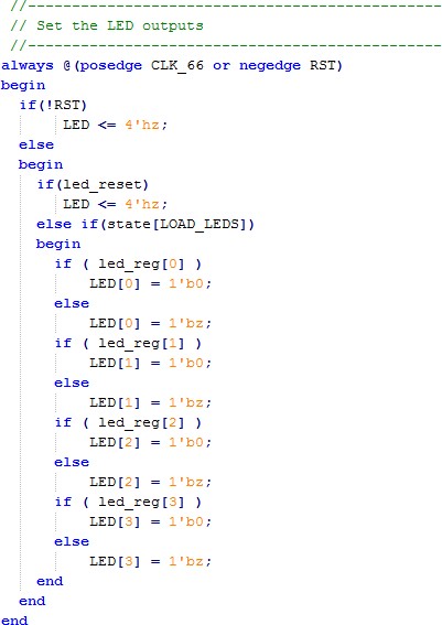
In the Set the LED Outputs block, the actual turn on/off value of the LED’s are set. This occurs when the state machine cycles around to state[LOAD_LEDS]. In the first if statement of the synchronous part of the block, the value of led_reset is checked. The led_reset signal is asserted when the user selects the LED Reset function in the C# application. It is sent to the CPLD as part of the Control Register. If the led_reset is high, the state of the LED’s is set to high impedance. The high impedance state of the LED’s will effectively turn them off. This is so, because anode is tied to +5V and the cathode is controlled by the CPLD pin. So, ‘floating’ the CPLD pin will cause no current to flow through the LED and thus turning it off. If the CPLD pin is set to low or zero, this will complete the LED circuit and current will flow through the LED and thusly turn it on.
In the second if statement of the block, the state[LOAD_LEDS] will cause four individual if statements to execute. Each if statement checks an individual bit of the led_reg. If the a bit is high, the corresponding bit of the LED pin goes low. If not, the corresponding LED pin goes into high impedance.
-
Transfer Control Register State Machine
The led_reset signal and LED function selection is set by using the active_control_register module. The Control Register is activated by sending a sequence of three special bytes to the Transfer EndTerm with address 2. The sequence of bytes is:
-
TRANSFER_CONTROL_BYTE1 = 8'h5A;
-
TRANSFER_CONTROL_BYTE2 = 8'hC3;
-
TRANSFER_CONTORL_BYTE3 = 8’h7E
A state machine in the active_control_register.v file decodes this sequence and captures the fourth byte as the control register. The bits of the Control Register are defined below.
Register
Bits
Description
Assertion
Control
0
Not Used
1
Not Used
2
led_reset
High
3
Not Used
4
LED Blinky Function Bit 0
5
LED Blinky Function Bit 1
6
LED Blinky Function Bit 2
7
LED Blinky Function Bit 3
-
-
Send Pattern to LED’s State Machine
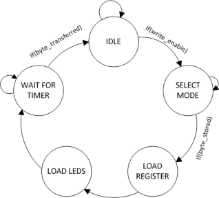
The Send Pattern to LED’s State Machine is a high speed Finite State Machine (FSM). It is a two always statement one-hot finite state machine. It is used here because it provides high speed glitch free operation. One hot means that it has one register for each state. The two always block setup allows a synchronous operation to be relegated to moving the state machine to the next state.
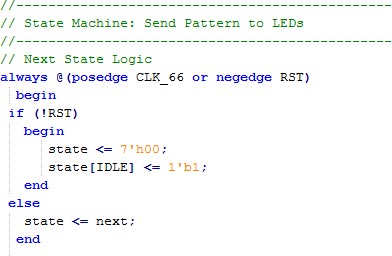
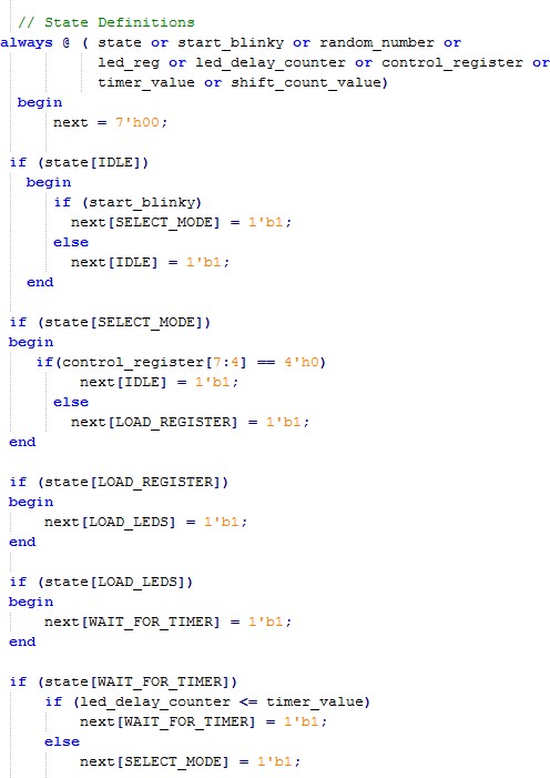
An asynchronous always block is used to select which state will be the next state. All of the outputs are handled in their own always blocks and separate from the state machine.
This asynchronous always block is the one which causes the state machines conditional branches to update. If the conditional branches are not updated with the correct inputs, then the next[…] statement will not get updated with the correct state and the state machine could get stuck in the wrong state. So, each input into the state machine MUST be entered into the sensitivity list of the “State Defiinitions” always block.
-
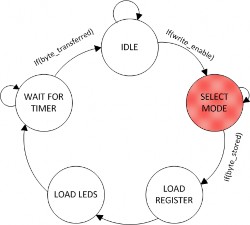
The state machine stays in state[IDLE] until the start_blinky signal goes high. When this signal goes high, the state machine goes into state[SELECT_MODE].
-
In state[SELECT_MODE], the Control Register is used to select the mode to put the LED’s in. This state causes the led_reg to latch an LED function from the Control Register. The led_delay_counter value is also latched from the timer_value. This state has a conditional branch, so it either proceeds to state[LOAD_REGISTER] of state[IDLE] based on the value of the Control Register.
-
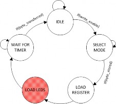
The next state is state[LOAD_REGISTER]. In this state the shift_count_value is shifted or incremented depending on the LED function. This state has no conditional. So at the next clock cycle, it increments to the next state.
-
The state machine progresses to state[LOAD_LEDS] and causes the value of led_reg to be loaded into LED’s. This state has no conditional. So at the next clock cycle, it increments to the next state.
-
In state[WAIT_FOR_TIMER] the led_delay_counter starts counting down from the timer_value. It stays in this state until led_delay_counter cycles below zero and becomes 0xFFFFF FFFF FFF. This state has a conditional branch that causes the state machine to stay in the state[WAIT_FOR_TIMER] and waits until the led_delay_counter is greater than timer_value. When that happens, the state machine branches to the state[SELECT_MODE] .
-
At the second branch into the state[SELECT_MODE], a conditional branch is checked. If the top four bits of the control register are zero, the state machine goes to state[IDLE]. And the process starts over.
-
-
Linear Feedback Shift Register Instantiation
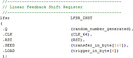
The Linear Feedback Shift Register is a separate module stored in its own file, lfsr.v. To access the module we have to use a leaf instantiation. In the leaf instantiation, you can match the ports by name or position. The name of each port is placed on the left hand side preceded by a ‘.’ And the local signal is placed in on the right hand side inside parenthesis. The name of the module goes on the left hand side while the local name of the instantiation goes on the right hand side.
The lfsr module provides a random single bit based on the input clock. The lfsr must be loaded with a four bit seed value. This seed value is latched into the lfsr by transferring a byte using the Transfer EndTerm from the C# application and using Trigger EndTerm bit 7. The seed value needs only four bits so the transfer_in_byte[3:0] is set on the input port “SEED”. The output of the lfsr is placed in the random_number_generated signal.
-
Control Register from Transfer In State Machine Instantiation
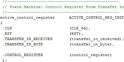
The Active Control Register module provides a simple means of sending an eight bit register to the CPLD code to control things like resetting the LED’s or sending the LED function. It is a standalone module that uses the Transfer EndTerm with address 2. It uses few registers so it is a good alternative to using a second more resource hungry Transfer EndTerm. It works by sending a series of three pre-determined bytes from the C# application to Transfer EndTerm with address2. These bytes are directed into the Active Control Register module. Inside the module, there is a state machine that increments states based on receiving each one of the known bytes. The bytes must be received in order or else the state machine resets and starts over. The fourth byte sent into the module is latched into the Control Register. The ports into the module are CLK, RST, TRANSFER_IN_RECEIVED, and TRANSFER_IN_BYTE.
-
EndTerm Instantiation
Next, up is the instantiation for the active_transfer_library. The ports include the input and output pins and the two buses that connect the active modules. These buses are the input UC_IN[23:0] and output UC_OUT[21:0].
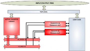
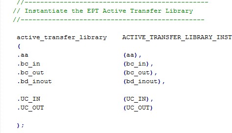
Finally, we instantiate the EndTerms. For the Fast LED Blinky project, we only need active_transfer and active_trigger EndTerms. The uc_out port for both modules must be shared. Since they both drive this bus, a bus wide wired-or circuit is used so that they don’t drive each other. The active_transfer EndTerm has a port for the address (uc_addr). This allows the PC to address up to 8 different modules. Just add a three bit address to this port and the PC must add this same address to communicate with this module.
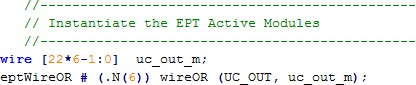
The Active_Trigger Instantiation allows the individual trigger bits to be set in the User code. They also allow the User code to set trigger bits in the C# application. Instantiate it using the wire or’ed uc_out_m bus.
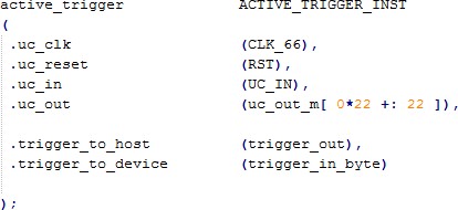
Next, the Transfer EndTerm is instantiated. Add the leaf instantiation with the address fixed at 2 for the EndTerm. Add the start_transfer, transfer_busy and transf_out_byte to control the transmission of the digitized value across the USB.
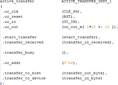
The “endmodule” signifies the module is done and no more code is allowed beyond that point.
Next, we are ready to compile and synthesize.
-
Compile/Synthesize the Project
The Quartus II application will compile/ synthesize the user code, active_transfer_library, and the Active EndTerms. The result of this step is a file containing the CPLD code with “*.pof”. First, we need to create a project in the Quartus II environment. Follow the directions in the section: “Compiling, Synthesizing, and Programming CPLD” of the User Manual.
Bring up Quartus II, then use Windows Explorer to browse to c:/altera/xxx/quartus/qdesigns create a new directory called: “EPT_Fast_LED_Blinky”.
Open Quartus II by clicking on the icon .

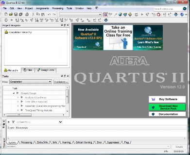
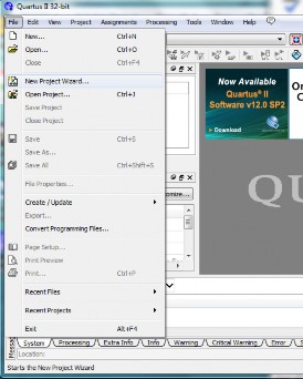
Under Quartus, Select File->New Project Wizard. The Wizard will walk you through setting up files and directories for your project.

At the Top-Level Entity page, browse to the c:\altera\xxx\quartus\qdesigns\EPT_Fast_LED_Blinky directory to store your project. Type in a name for your project “EPT_570_AP_U2_Top”.
Follow the steps up to Add Files. At the Add Files box, click on the Browse button and navigate to the project Fast LED Blinky install folder in the dialog box. Browse to the
\Projects_HDL\EPT_ Fast LED Blinky\EPT_570_AP_U2_Top folder of the USB_CPLD_FAST_LED_BLINKY_PROJECT_CD . Copy the files from the \src directory.
-
Active_transfer.vqm
-
Active_trigger.vqm
-
Active_transfer_library.vqm
-
eptWireOr.v
-
ETP_570_AP_U2_Top.v Add the files:
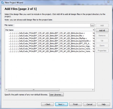
Select Next, at the Device Family group, select MAX II for Family. In the Available Devices group, browse down to EPM570T100C5 for Name.
Select Next, leave defaults for the EDA Tool Settings.
Select Next, then select Finish. You are done with the project level selections.
-
-
Synthesizing
With the project created, we need to assign pins to the project. The signals defined in the top level file (in this case: EPT_570_AP_U2_Top.v) will connect directly to pins on the CPLD. The Pin Planner Tool from Quartus II will add the pins and check to verify that our pin selections do not violate any restrictions of the device. In the case of this example we will import pin assignments that created at an earlier time. Under Assignments, Select Import Assignments.

At the Import Assignment dialog box, Browse to the \Projects_HDL\EPT_ Fast LED Blinky\Altera_EPM570_U2 folder of the USB_CPLD_FAST_LED_BLINKY_PROJECT_CD. Select the “EPT_570_AP_U2_Top.qsf” file.

Next, we need to add the Synopsys Design Constraint file. This file contains timing constraints which forces the built in tool called TimeQuest Timing Analyzer to analyze the path of the synthesized HDL code with setup and hold times of the internal registers. It takes note of any path that may be too long to appropriately meet the timing qualifications. For more information on TimeQuest Timing Analyzer, see
http://www.altera.com/literature/hb/qts/qts_qii53018.pdf?GSA_pos=1&WT.oss_r=1& WT.oss=TimeQuest Timing Analyzer
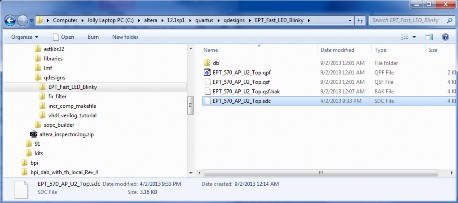
Browse to the \Projects_HDL\EPT_ Fast LED Blinky\Altera_EPM570_U2 folder of the USB_CPLD_FAST_LED_BLINKY_PROJECT_CD. Select the “EPT_570_AP_U2_Top.sdc” file.

Copy the file and browse to c:\altera\xxx\quartus\qdesigns\EPT_Fast_LED_Blinky directory. Paste the file.
and select the Start Compilation button.

This will cause the compile and synthesization process. After successful completion, the screen should look like the following:
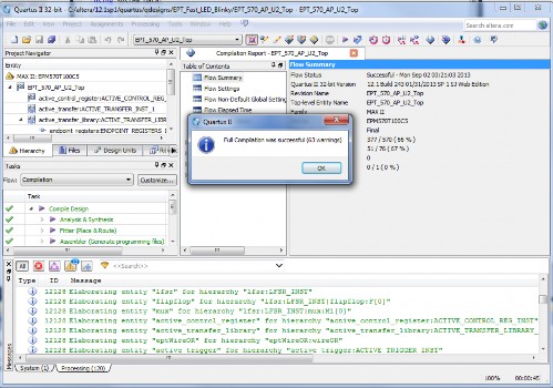
If the synthesis fails, you will see the failure message in the message window. Note that in addition to fatal errors, the compile process can produce “warnings” which do not necessarily prevent execution of the code but which should be corrected eventually.
At this point the project has been successfully compiled, synthesized and a programming file has been produced. See the next section on how to program the CPLD.
-
Program the CPLD
The final step is programming the “*.pof” file into the CPLD.

-
Connect the UnoProLogic to the PC,
-
Open up Quartus II,
-
Open the programmer tool
If the project created in the previous sections is not open, open it. Click on the Programmer button.
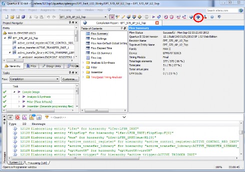
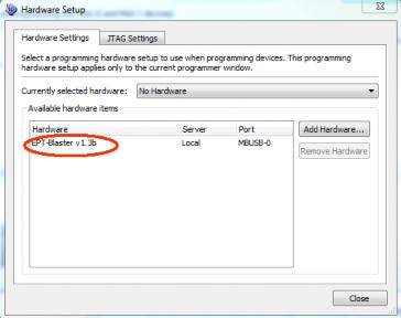
The Programmer Window will open up with the programming file selected. Click on the Hardware Setup button in the upper left corner.
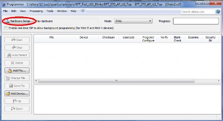
The Hardware Setup Window will open. In the “Available hardware items”, double click on “EPT-Blaster v1.3b”.
If you successfully double clicked, the “Currently selected hardware:” dropdown box will show the “EPT-Blaster v1.3b”.
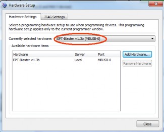
Click the “Close” button.
Next, selet the checkbox under the “Program/Configure” of the Programmer Tool. The checkboxes for the CFM and UFM will be selected automatically.
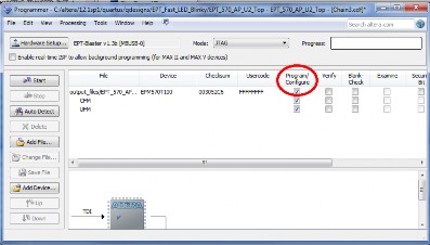
Click on the Start button to to start programming the CPLD. The Progress bar will indicate the progress of programming.

When the programming is complete, the Progress bar will indicate success.

At this point, the UnoProLogic is programmed and ready for use.
-
-
-
PC: C# Project Design
The final piece of the Fast LED Blinky Project is the PC application. This application will fetch the data from the CPLD of the UnoProLogic and display it on the screen. It includes user code, windows form, and the Active_Host DLL.

The Active_Host DLL is designed to transfer data from the CPLD when it becomes available. The data will be stored into local memory of the PC, and an event will be triggered to inform the user code that data is available from the addressed module of the CPLD. This method, from the user code on the PC, makes the data transfer transparent. The data just appears in memory and the user code will direct the data to a textbox on the Windows Form.
The Fast LED Blinky project will perform the following functions.
-
Find UnoProLogic Device.
-
Open UnoProLogic Device.
-
Select an LED function.
-
Send function to CPLD.
-
Send Delay Timer to CPLD.
-
Send LED static value to CPLD.
-
Display LED status from CPLD on LED buttons.
-
Coding the C# Project
The user code is based on the .NET Framework and written in C#. The language is great for beginners as it is a subset of the C++ language. It has the look and feel of the familiar C language but adds the ease of use of classes, inheritance and method overloading. C# is an event based language which changes the method of writing code for this project. You will need to get some background knowledge in coding with C#
and the .NET Framework on the PC. For a better description of event based language programming and C#, see the following for a tutorial
http://www.homeandlearn.co.uk/csharp/csharp.html
-
C# Project Creation
To start the project, use the wizard to create project called “EPT_Fast_LED_Blinky”. When the wizard completes, the C# Express main window will look like the following.
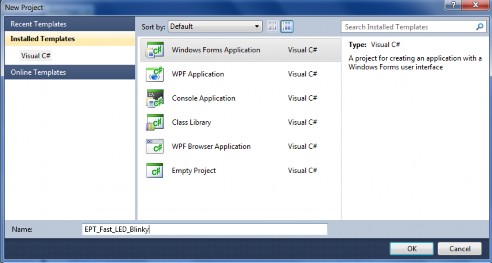
The setup statements create the namespace and the class for the project. There are several other files that are created by the wizard such as Form1.Designer.cs, Program.cs, Form1.resx. We don’t need to go into these support files, we will just focus on the Form1.cs as this is where all the user code goes.
Click on File->Save “EPT_Fast_LED_Blinky as. Browse to C:\Users\<user name>\Documents\Visual Studio 2010\Projects, and click Select Folder. Click the Save button.
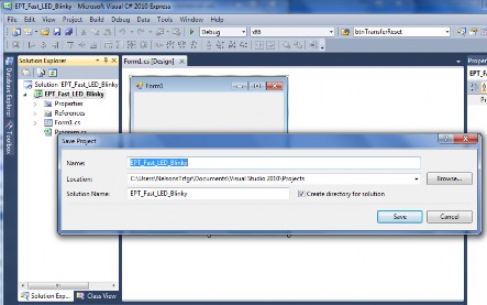
Locate the \Projects_ActiveHost_64Bit\EPT_Fast_LED_Blinky\ folder in the USB_CPLD_FAST_LED_BLINKY_PROJECT_CD. Copy the following files:
-
active_transfer_x64.cs
-
Form1.cs
-
Form1.Designer.cs
-
Form1.resx
-
Program.cs
Open a Windows Explorer window and browse to C:\Users\NelsonsTrfgr\Documents\Visual Studio 2010 \Projects
\EPT_Fast_LED_Blinky \EPT_Fast_LED_Blinky. Paste the files to this folder.

In the Solution Explorer Window, right click on the project name, EPT_Fast_LED_Blinky and select Add->Existing Item
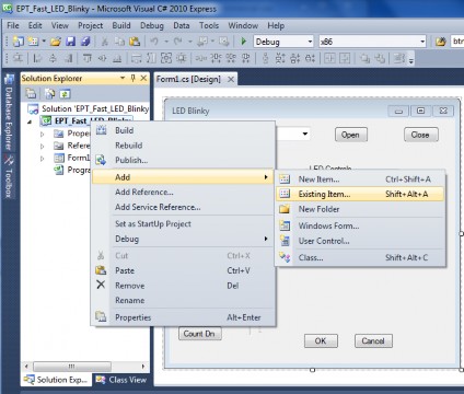
Select the following file:
-
active_transfer_x64.cs Click Add.
-
-
C# Project Environment Setup
The project environment must be set up correctly in order to produce an application that runs correctly on the target platform. Visual C# Express defaults new projects to 32 bits. If your OS is a 64 bit platform, use the following directions to set up a 64 bit project.
First, we need tell C# Express to produce 64 bit code if we are running on a x64 platform. Go to Tools->Settings and select Expert Settings
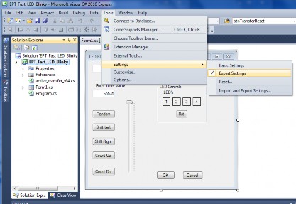
Go to Tools->Options, locate the “Show all settings” check box. Check the box.
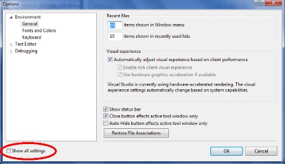
In the window on the left, go to “Projects and Solutions”. Locate the “Show advanced build configurations” check box. Check the box.

Go to Build->Configuration Manager.
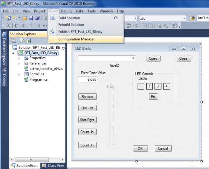
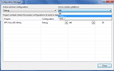
In the Configuration Manager window, locate the “Active solution platform:” label, select “New” from the drop down box.
In the New Solution Platform window, click on the drop down box under “Type or select the new platform:” and select “x64”.
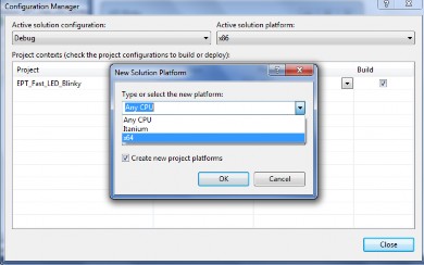
Click the Ok button. Verify that the “Active Solution Platform” and the “Platform” tab are both showing “x64”.

Click Close.
Then, using the Solution Explorer, you can right click on the project, select Properties and click on the Build tab on the right of the properties window.
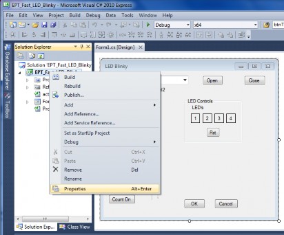
Verify that the “Platform:” label has “Active (x64)” selected from the drop down box.
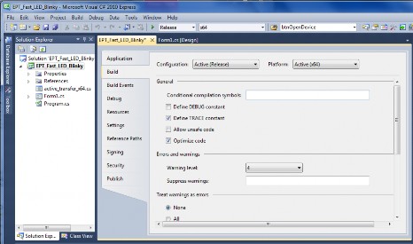
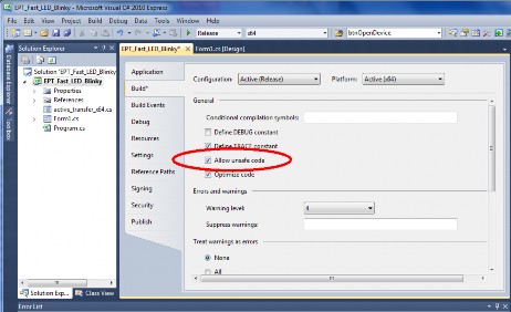
Next, unsafe code needs to be allowed so that C# can be passed pointer values from the Active Host.
Locate the “Allow unsafe code” check box. Check the box
-
Project Parameters
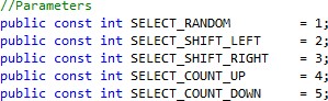
The C# application requires the use of some constant parameters. The first group is used by the switch statement in the callback function to select which EndTerm caused the callback function to be called.

The second group of parameters is used to select which LED functioni to send to the CPLD.
-
C# Object Initialization
Now we are ready to start coding.
Next, we add two classes for our device. One class stores the information useful for our device for Transmit to the EndTerms such as, address of module, length of transfer etc.

The next class is used to store parameters for receiving data from the device.


The first function called when the Windows Form loads up is the EPT_Fast_LED_Blinky _Load(). This function is called automatically upon the completion of the Windows Form, so there is no need to do anything to call it.
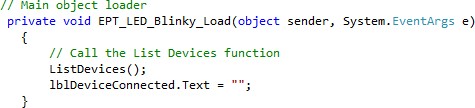
Once this function is called, it in turn calls the ListDevices().
-
C# Project Select Devices
The ListDevices() function calls the EPT_AH_Open() function to load up the

ActiveHost Dll. Next, it calls EPT_AH_QueryDevices() which searches through the registry files to determine the number of EPT devices attached to the PC. Next, EPT_AH_GetDeviceName() is called inside a for loop to return the ASCII name of each device attached to the PC. It will automatically populate the combo box, cmbDevList with all the EPT devices it finds.
-
C# Project Open Device
The user will select the device from the drop down combo box. This value will be sent
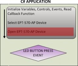
to the OpenDevice() function using the button Click of the Open button.
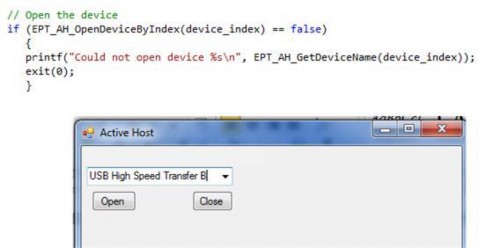
The device_index variable is used to store the index of the device selected from the combo box. This variable is passed into the EPT_AH_OpenDeviceByIndex(). This process is started by the user clicking on the “Open” button. If the function is successful, the device name is displayed in the label, labelDeviceCnt. Next, the device is made the active device and the call back function is registered using the RegisterCallBack() function. Finally, the Open button is grayed out and the Close button is made active.
-
C# Project Callback Initialization
The callback function is populated. This function will be called from the Active Host dll. When the EPT Device has transferred data to the PC, the callback function will do something with the data and command.

Because the callback function communicates directly with the dll and must pass pointers from the dll to the C#, marshaling must be used. Marshaling is an advanced C# topic and will not be covered in this manual. We will let the callback function work in the background and we only need to use the EPTParseReceive() function to handle incoming data.
-
C# Project Controls
Controls such as buttons are added to the Form1.cs[Design] window which allow turning on and off signals. These include
-
btnOk
-
btnCancel
-
btnOpenDevice
-
btnCloseDevice
-
btnLEDReset
-
btnTrigger4
-
btnTrigger3
-
btnTrigger2
-
btnTrigger1
-
btnShiftLeft
-
btnShiftRight
-
btnCountUp
-
btnCountDown
-
btnRandom
Textboxes are used to display information on the Windows form. These textboxes are:
-
cmbDevList
-
tbTimerValue
-
-
C# Project Buttons
Although, the C# language is very similar to C Code, there are a few major differences. The first is C# .NET environment is event based. A second is C# utilizes classes. This guide will keep the details of these items hidden to keep things simple. However, a brief introduction to events and classes will allow the beginner to create effective programs.
Event based programming means the software responds to events created by the user, a timer event, external events such as serial communication into PC, internal events such as the OS, or other events. The events we are concerned with for our example program are button clicks or dropdown box clicks. The user events occur when the user clicks on a button on the Windows Form or selects a radio button.
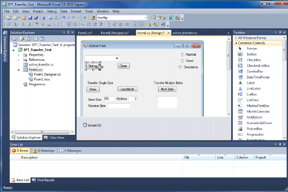
The callback function will be inserted with the name of the button along with “_click” appended to it. The parameter list includes (object sender, System.EventArgs e). These two additions are required for the callback function to initiate when the “click” event occurs.

There is one more addition to the project files. Double click on the Form1.Designer.cs file in the Solution Explorer. Locate the following section of code.
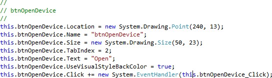
This code sets up the button, size, placement, and text. It also declares the “System.EventHandler()”. This statement sets the click method (which is a member of the button class) of the btnOpenDevice button to call the EventHandler – btnOpenDevice_Click. This is where the magic of the button click event happens.
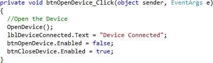
When btnOpenDevice_Click is called, it calls the function “OpenDevice()”. This function is defined in the dll and will connect to the device selected in the combo box. This is a quick view of how to create, add files, and add controls to a C# project. The user is encouraged to spend some time reviewing the online tutorial at http://www.homeandlearn.co.uk/csharp/csharp.html to become intimately familiar with Visual C# .NET programming. In the meantime, follow the examples from the Terranologic to perform some simple reads and writes to the EPT USB-CPLD Development System.
The btnCloseDevice_Click is called when the user clicks on the Close button in the C# application. This code calls the

This closes the ActiveHost dll connection to the UnoProLogic. This event also sets the the button to specific states at the close of the device.

The btnOk and btnClose buttons are used to end the application. It calls the function EPT_AH_CloseDeviceByIndex() to remove the device from the Active Host dll. The
buttons btnOpen and btnClose have their Enabled parameter set to true and false respectively. The Enabled parameter controls whether the button is allowed to launch an event or not. If it is not enabled, the button is grayed out. At the end of each click event, the Application.Exit() method is called. This exits the form.

They both operate on the click event, which are setup in the Form1.Designer.cs file

-
LED On/Off Control

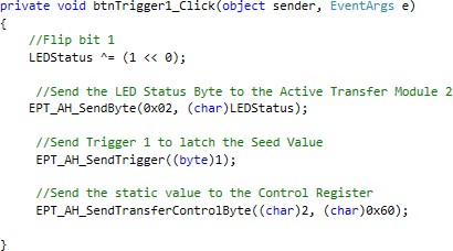
The btnTrigger1, 2, 3 and 4 are used to select the inverse of the current state of their respective LEDs and send it to the UnoProLogic via EndTerm USB Trasnfer. Each function first inverts the LEDStatus variable, then calls the function

This will send the LEDStatus byte to the CPLD. Next, call the function:

This latches the LEDStatus byte into a local register int eh CPLD.
Next, the EPT_AH_SendTransferControlByte() is called to set the LED Function, 0x60 in the control register. The function passes the control byte to the Active Host dll.
The EPT_AH_SendTransferControlByte() requires two parameters, address and control register. The address must correspond to the correct EndTerm in the UnoProLogic code.
-
LED Reset
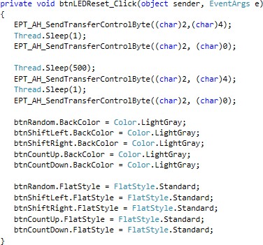
The LED Reset function will send a command to the CPLD in the Control Register to turn off all four LED’s. The Control Register is not self resetting, so the command must be sent to assert the LED Reset and then send a second command to de-assert the LED Reset.

Next, the btnLEDReset function will set the color and style of each of the LED FunctionButtons. This is done because the LED Function’s take the color of on or off when commanded. So, when the reset is sent to the LED’s, the color is changed to gray for each button. Also, the sytel is set to FlatStyle. Standard for each button.
-
Load Timer Value
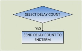
The LoadTimerValue() function is called anytime an LED Function is selected or the track bar slider is moved. It will send two bytes to the CPLD and latch each one into a different section of the timer register. The first thing this function does when called is to get the current value of the Timer Value. It does this by puttting the string from the textbox: tbTimerValue into the integer intValue. Then, converting intValue into an array of bytes.

Next, send the first byte in the array to the Transfer EndTerm using the function:

Latch this value intot he CPLD timer register using the Trigger EndTerm.

Repeat this process for the next byte in the CPLD timer register.

-
Track Bar Timer
The trkbrTimer function is called whenever, the scroll bar is moved. It determines the current value of the timer which will be between 1000 and 65535. It then places this value into the textbox, tbTimerValue. When this is complete, it call LoadTimerValue() to send the new timer value to the CPLD.
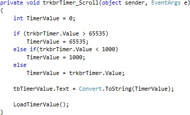
The code to get the value of the value of the track bar is

Adding the “.Value” to the end of the trkbrTimer invokes the get parameter value from the track bar. This is a member of the track bar class. This value can be passed on to the text box. However, we need to condition this timer value because we don’t want to send more than 16 bits to the CPLD timer register. Also, we don’t want to send less that 1000, because this is too fast for the LED Blinky controller to handle. Notice the CPLD can send data much faster than the C# application can handle. So, we add the conditional code to keep TimerValue within these limits.

Next, populate the text box with TimerValue.

Then call the LoadTimerValue() function to update the timer register in the CPLD.

-
The LED Function Selection

The Fast LED Blinky Controller allows the user to select LED functions. There are five LED Function buttons.
-
Random
-
Shift Left
-
Shift Right
-
Count Up
-
Count Down
To send an LED Function to the CPLD, the C# application must send the timer value, send the LED status, send the Trigger EndTerm to latch the function, send the LED function, and finally sest the correct color of all buttons on the window form.
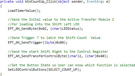
The LED Functions are selected by the top four bits of the Control Register.
Function
Control Register Byte
Random
0x10
Shift Left
0x20
Shift Right
0x30
Count Up
0x40
Count Down
0x50
-
-
Set LED Control Buttons
The SetLEDControlButtons() function is called by the LED Function Selects in order to set the color and style of the Function buttons. This is done so that when a function is selected, its function button is changed in color. The calling function must provide a selection from the parameters defined in the parameters/constant section of the code at the top.

In the SetLEDControlButtons() function, a switch statement uses the selection from the calling function to determine which buttons need to be changed to which colors.

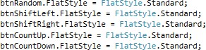
The function that was selected gets its button color changed to “LightSteelBlue”. While the rest of the buttons are “LightGray”. After the switch statement completes execution, the style for each button is reset.
-
C# Project EPTReadFunction Callback
The CPLD will send the LED Status from the current state of the LED’s once during its state machine cycle. When this happens, the ActiveHost dll accesses and stores this LED Status. It also generates a call to the callback function. When the EPTReadFunction() callback is called and passed parameters from the Active

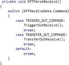
Host dll, it populates the EPTReceiveData object with the Command, Address, Payload and other parameters. It then calls EPTParseReceive() function. This function uses a switch statement to determine which EndTerm was accessed (in the code it is noted as the “Command”). Then, the TransferOutReceive() function is called based on the EndTerm(Command).
-
TransferOutReceive Function
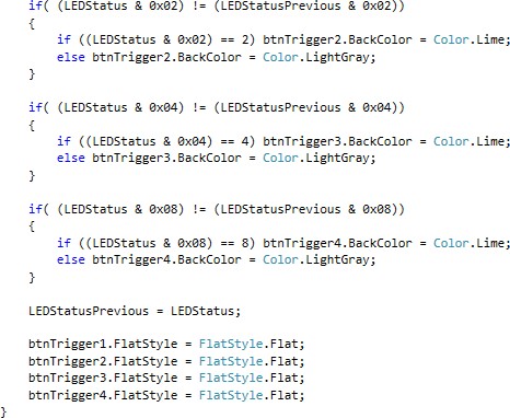
TransferOutReceive() is the function that decodes the Transfer EndTerm message, selects the LED and updates the color of the LED button on the Windows form. The LEDStatus variable takes the value from the EPTReceiveData object.

Then the LEDStatus is checked with a series of “if” conditional statements. The LED Status byte is compared to each single bit position in the LED block to determine

if it has changed (on/off) from the previous LED Status update. If it has changed, the color of the LED button is changed appropriately. If the LED bit is high, then change the color to “Lime”. Else, the LED bit is low and change the color to “LightGray”.

At the end of the function, the LEDStatusPrevious variable takes the value of the

LEDStatus. This will be used in the time the callback function is called to determine the change in LED Status.

-
C# Project Completion
This is all that is needed for the Fast LED Blinky project. The user selects the delay timer value, the LED status and the LED function then transmits this information to the CPLD using the Transfer and Trigger EndTerms. The CPLD uses these values to select the LED function, and timer value to apply to the One Hot State Machine. The Active Host dll calls the Callback function, which updates the current state of the LED’s on the Windows Form.
-
-
PC: Compiling the Active Host Application
Building the Fast LED Blinky project will compile the code in the project and produce an executable file. It will link all of the functions declared in the opening of the Fast LED Blinky Class with the Active Host dll. The project will also automatically link the FTD2XX.dll to the object code.
To build the project, go to Debug->Build Solution.
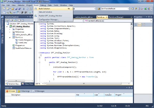
The C# Express compiler will start the building process. If there are no errors with code syntax, function usage, or linking, then the environment responds with “Build Succeeded”.

If the build fails, you will have to examine each error in the “Error List” and fix it accordingly. If you cannot fix the error using troubleshooting methods, post a topic in the Terranologic Forum. All topics will be answered by a member of the technical staff as soon as possible.
-
Adding the DLL’s to the Project
Locate the USB_CPLD_FAST_LED_BLINKY_PROJECT_CD installed on your PC. Browse to the Projects_ActiveHost folder (choose either the 32 bit or 64 bit version, depending on whether your OS is 32 or 64 bit). Open the Bin folder, copy the following files:
-
ActiveHostXX.dll
-
ftd2xxXX.dll
and paste them in the EPT_Fast_LED_Blinky\EPT_Fast_LED_Blinky\bin\x64\Release folder of your EPT_Fast_LED_Blinky project.
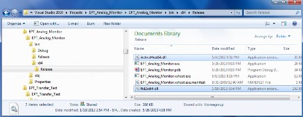
At this point, the environment has produced an executable file and is ready for testing. Next, we will connect everything together and see it collect data and display it.
-
-
-
Testing the Project
-
To test our Fast LED Blinky project, make sure the UnoProLogic is connected to a USB port with a Mini B cable. Go to the folder Projects_ActiveHost_xxBit\EPT_Fast_LED_Blinky\EPT_Fast_LED_Blinky\bin\x64\R elease in the USB_CPLD_FAST_LED_BLINKY_PROJECT_CD.
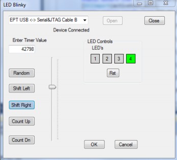
Click on the EPT_Fast_LED_Blinky.exe file. The Windows Form will open up. Located the EPT USB <-> Serial&JTAG Cable B in the drop down combo box at the top. Click on the Open button. Next, click on one of the LED’s in the LED Controls Group. Select a function like the Shift Right. Slide the track bar timer value down to
some value in the 40,000’s. You should see the LED’s in the LED Controls Group shifting one LED to the right. Also, you should see the LED’s on the UnoProLogic shifting right.
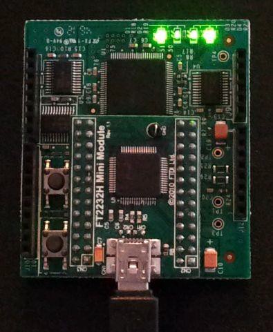
And that’s all there is to the Fast LED Blinky Project. You can select other functions and see how the shifting or counting changes the LED’s. Also, adjust the track bar timer to see how fast the LED’s can shift or count.